Category Archives: Electric Brewing

Posts about building an electric brew system

Mini-BIAB Electric Turkey Fryer Mod–Part 3

Now that I have finished putting together the necessary circuits to read the thermistor and control the heating element, I need to provide some simple circuits for the user interface.

The Front Panel

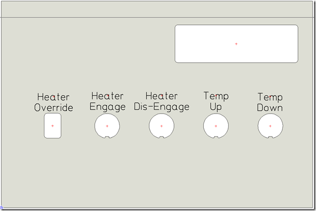
Below is a mock up of what I want the front panel to look like:

ControlPanel

At the top right I will have a 16×2 LCD Display with a series of switches to control the heating element and set temperature for the temperature monitoring service.

  1. Heater Override – This switch will allow the user to cut off the return signal from the main circuit board back the Turkey Fryer 12V Relay to keep from accidentally dry firing the heating element.
  2. Heater Engage – This push button is used to signal the Netduino that the heater can be engaged and until pushed will not allow the Temperature Service to turn the heating element on.
  3. Heater Dis-Engage – This push button is used to signal the Netduino that the heater should be dis-engaged immediately, kind of like an all-stop button.
  4. Temp Up – This push button will raise the temperature monitoring service’s set temperature by one degree.
  5. Temp Down – This push button will lower the temperature monitoring service’s set temperature by one degree.

This is a pretty simple interface, but it provides all the basic necessities to control the Turkey Fryer during a brewing session.

The Main Board Connections

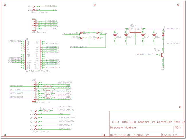
Below is the schematic for the main circuit board of the system along the right hand side you can see the various connectors that will be used to wire the switches into the Netduino:

Main_Board_Schematic

I have wired each of the push button switches using a pull-down resistor configuration, this keeps the signal to the Netduino ports low until the push buttons are pushed connecting the ports to 3.3V. The switch connections are wired into a series of header pins that will be used to connect each switch to the main board.

I have also ran Netduino Pin5 to a second screw terminal that connects to a Peizo speaker that is used to provide an audible signal when the temperature of the Fryer reaches the set temperature and again when a mash step completes. I’ll explain the code in a later post.

There is one last connector in the upper left of the schematic and this one connects the main circuit board to the LCD Display Daughter board. This connector extends the Netduino SPI ports 10, 11 and 13 to the daughter board along with 5V and Ground which are used to power the LCD Display.

In the next post I’ll cover the LCD Display Daughter Board and how you can use 3 Netduino pins to drive a 16 x 2 LCD Display.

Till next time, stay sanitized and keep an eye on those fermentation temps and I’ll catch you for a pint around the keg.

Jim Lavin – Otaku Brewer

Mini-BIAB Electric Turkey Fryer Mod–Part 2

It’s been a while since I started modding out the Electric Turkey Fryer to build out an Electric Brew In A Bag System. Between work, brewing for competitions and several other activities I finally got to spend the last couple of weeks finishing up the research to get the system up and running.

My major goal for this project was to use as much of the existing components from the Turkey Fryer, yet increase the precision of the temperature monitoring and control of the heating element to make the system as accurate as possible to handle a multi-step mash profile required for brewing good beer. To do this I needed to figure out what kind of thermistor the existing heating element had and build out the appropriate circuits to monitor the temperature and drive the existing relay and heating element.

Cracking the Thermistor

There are a lot of links on the internet for the Fryer unit, but all of them are mostly basic usage documentation about the unit, I couldn’t find anything that told me what type of thermistor was being used by the system. So I had to reverse engineer the unit so I could get some type of idea what I was dealing with.

For those of you who are new to electronics or sensors, there are two types of thermistors generally available, Positive Temperature Coefficient (PTC) and Negative Temperature Coefficient (NTC). You can identify the type of thermistor by it’s resistance curve as you heat it up, if the resistance rises with heat, it’s a PTC thermistor, if the resistance drops with heat, you have a NTC thermistor. So I hooked up my multi-meter and held my SMD hot air gun to the probe and watched as the resistance dropped with the rise in temperature. Great! that meant I had a NTC thermistor, next I needed to come up with the proper coefficients so I could calculate the temperature based on the resistance.

Now this is easy to find if you know the manufacturer and model of the thermistor, but for me that information could not be found, so I had to come up with another way to get them. This involved hooking up the thermistor to my Netduino along with a second temperature probe that I knew how to read and then record the resistance values and the temperature values so I could calculate the coefficients using the tools from the Thermistor Library on sourceforge.net.

Once I had a set coefficients, I used the code over at Arduino Playground as a basis to read the thermistor using the analog input of the Netduino and repeated the process of capturing resistance and temperature values until I got a set of coefficients that gave me temperature readings that matched my other probe.

My circuit ended up being a voltage divider using two resistors in series with the thermistor and taking the analog reading from the middle of the ladder. The resistance I ended up using for the second half of the ladder was 1.47M ohms. This needed to be as close to the 1.5M ohms that the thermistor reads at 25C/75F which is considered the base resistance for the thermistor. This way both resistances should provide equal values at the base temperature which is needed by the Stein-Hart quadratic polynomial equation used to calculate the temperature at a given resistance.

You can see the schematic for the circuit later in this article. Look for the Fryer Connector in the lower left of the schematic.

Driving the Relay

Next I needed to drive the relay which in turn would switch power to the heating element. The existing Fryer Control Unit used the 12V AC from the transformer and converted it to 12V DC to switch the relay on and off. I figured this would be perfect for me as well.

One thing you can’t easily do is use voltages greater than 3.3V with the Netduino controller, so I need to use a transistor to switch the 12V DC on and off to power the relay. This way I could safely drive the relay with a higher voltage without worrying about the Netduino.

I also needed to convert the 12V AC to 12V DC so I didn’t have to have yet another power source to drive the relay. Well this was pretty simple, all I needed was a bridge rectifier built from 4 diodes, a couple of capacitors to filter out the resulting wave and then run it through a power regulator to get a nice 12V DC output.

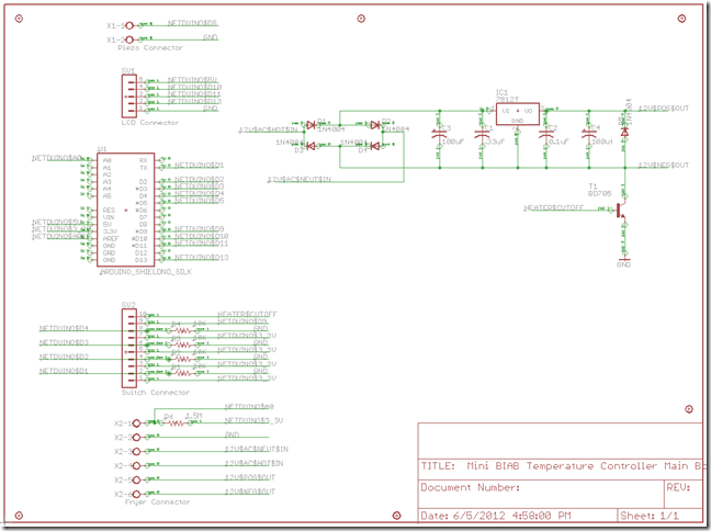
After a little research I came up with the circuit below on the right:
Main_Board_Schematic

As you can see I apply the 12V AC signal to the bridge created by the diodes and then filter the resulting signal through a 100uF polarized capacitor and then with a .33uF capacitor before it connects to the the LM7812 voltage regulator. The output is then filtered with a .1uF capacitor along with a second 100uF polarized capacitor. The .33uF and .1uF capacitance values come straight from the LM7812 datasheet. The other two came from some rough calculations to ensure I had enough voltage stored to smooth out the voltage dips between the peaks in the modified output created by the bridge rectifier. I also cheated a little and pulled the values of the capacitors from the original control board when it looked like my calculations of 400uF was going to be a little too much.

The connection to the relay is then taken from the positive and negative leads of the filtered output. I then use a diode to prevent a reverse voltage on the circuit when the relay shuts down and the NPN transistor is used as a switch to allow the voltage to flow to the 12V relay when the Netduino raises Pin 9 high.

I also put a switch in series between Pin 9 of the Netduino and the transistor to provide a safety measure to make sure the system does not power up the heating element unintentionally. This was needed since the pins on the Netduino are all raised high when the unit powers up. Without it the relay could get power when the Netduino is powered on causing a dry fire burning the element out.

Connecting the Old to the New

With the circuit to drive the  relay and heating element and the circuit to read the thermistor complete, I needed a simple way that I could run the old connections to the Netduino.
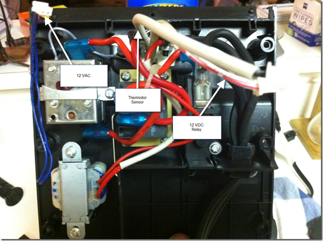
Temp_Controller_Connections

You might remember the picture above from my last post. Here you can clearly see that I needed to take 3 short leads and extend them to about 6 feet where the Netduino would be. To accomplish this I spliced the connections to the end of a Cat6 Ethernet cable. I used the following connections:

  1. 12V AC connections – Blue and Blue/White
  2. 12V DC connections – Orange and Orange/White
  3. Thermistor connections – Green and Green/White

The Ethernet cable is then connected to the breadboard via a RJ45 wall jack that connects to a series of screw terminals on the breadboard. You can see these connections in the schematic above in the lower left of the schematic labeled as Fryer Connector.

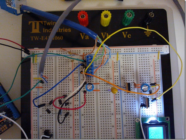
Here is a picture of the entire control circuit laid out on a breadboard connected to the Fryer:
WP_000089

You can see the RJ45 Connector coming into the screw terminals at the top along with the connections to the bridge rectifier and the return from the AC/DC Convertor on the right.

That’s about it for interfacing with the old Fryer Control Unit, In my next post I’ll discuss the Human Interface connections for the Temperature Controller as well as the LCD Display.

Till next time, stay sanitized and keep an eye on those fermentation temps and I’ll catch you for a pint around the keg.

Jim Lavin – Otaku Brewer

Mini-BIAB Electric Turkey Fryer Mod–Part 1

So, in my last couple of posts I was doing some research around coming up with the perfect Electric Counter-Top Brewing System. I found what I thought would be a perfect Mini-Brew-in-a-Bag Electric System with the Cajun Injector Electric Fryer, however the Temperature Controller that comes with it could not maintain the temperature accuracy nor the range needed to brew the variety of beers I wanted to make.

So as any industrious DIYer would do, I took apart the Temperature Controller to see if I could modify it. There are six screws in the back of the unit along with two under the face plate that hold the housing together, once removed the housing can be snapped apart to get to the components inside.

Temp_Controller

As you can see in the diagram, there are several components that can be reused to drive the heating element from an external controller, all I needed to do is figure out what connects to what and build out a schematic that I can use to build a controller interface that I can drive with a Microcontroller.

The Safety Switch acts as a master switch for the incoming power, If the unit is not seated in the Cajun Injector slots for it, no power will flow to the unit. Now this is a pretty nice feature that cuts power to the heating element should you pull it out of the pot and set it to the side. You also don’t have to worry about dry firing the unit if it is not seated in the pot. However, you still have the dry fire issue when the unit is properly seated in the pot.

The Unit also contains what looks to be a GFCI Breaker that is wired to a probe that runs along side the heating element.

There is also a 12VDC Relay that controls turning the heating element on and off based on the control signal from the control panel.

Finally to power the control panel there is what looks like a reduction transformer that should provide the 12V power needed to drive the relay.

The control panel has an LCD mounted on it and what looks like a microcontroller or Programmable Logic Array which is the brains of the Temperature Controller. From a quick inspection it really doesn’t look like it contains  anything of use.

There were three connections from the control panel to the components in the housing. These look to be an input voltage, the Thermistor input connections and the Relay control outputs. I should be able to extend these to an external controller and drive the heating element.

Temp_Controller_Connections

I also performed a little research by hooking up the Thermistor to my Multi-meter and measured the resistance at several temperatures. What I got was a pretty broad range of resistance; 3.58 M ohms at 40 degrees F down to 80 K ohms at a rolling boil. Now without knowing the actual part number of the Thermistor I really didn’t think I could come up with a temperature curve that I could use to figure out the temperature based on the resistance. Luckily after a little searching on the Internets I came up with a program that would generate a set of temperature coefficients based on a couple of readings at known temperatures. With this, I plan on reverse engineering the temperature coefficients of the Thermistor so I can come up with a resistance curve that I can use to determine the temperature by using the Thermistor in a voltage divider and then calculating the temperature value based on a known voltage.

So my next steps are to do a little more poking around the components and determine the transformer’s output voltage is and start coming up with a plan to build out a controller board that I can use with a Netduino to drive the unit.

So stay sanitized and keep an eye on those fermentation temps and I’ll catch you for a pint around the keg.

Jim Lavin – Otaku Brewer
The Search for a Counter-Top Electric Brewing System – Part Two

In my last post, I talked about my goals to find a nice Counter-Top Electric Brewing System that I could do small 1 – 2 Gallon batches for competitions, while I finish out my big Electric Brew System. I also, talked about using a Coffee Urn and how it would be good for both a Hot Liquor Tank and Mash Tun, but really needed work for a Boil Kettle. This post covers my research into using an Electric Turkey Fryer to build a mini Brew-in-a-Bag system.

After coming across a couple of posts on the HomeBrewTalk Forums, I ordered a Cajun Injector Electric Turkey Fryer from Wal-Mart for $99. It looked pretty promising, 7 Gallon Capacity, All-In-One Heating Element with Temperature Controller and a metal straining basket.

fryer_1

My water tests showed that I could bring 4 Gallons of water to a temperature of 150 degrees F in just under 20 minutes, which is perfect for small batches. However, there were two fatal flaws.

First, I really was hoping I could set the Temperature Controller to a lower temperature, a lot of the more classic style mash regimes start the mash around 113 – 122 degrees F and then move up to 178 degrees F in various temperature steps. The controller comes with a minimum temperature of 150 degrees and the next temperature is 175 degrees F. Not really great if you want to be able to precisely control your mash temperatures.

Second, the temperature differential for the controller is around 5 – 10 degrees loss before the unit turns back on. This is way too wide of a differential to support an exact mash temperature. You really want to set a temperature and have the heating element kick back on when the temperature drops more than a degree.

As for bringing 4 gallons of water to a boil, I have no problem with it being able to do that. The 1650 Watt heating element can easily bring 4 Gallons of water to a boil in a reasonable amount of time.

So, this unit seems to have everything in what I want in a Counter-Top Electric Brewing System except for the tight temperature control. To gain that I think I’ll need to hack the Temperature Controller or replace it all together.

This makes for a perfect platform to experiment with temperature control and work out all the kinks of my temperature controller’s design before I try to apply it to a 10 Gallon system pushing 210 VAC around at 30 Amps.

So, I’ll keep everybody up to date as I start to hack the Temperature Controller on the Cajun Injector Electric Fryer.

The Search for a Counter-Top Electric Brewing System

While I’m busy working on my full-scale all-electric brewing system, I figured it be nice to have a small counter-top electric brew system that I could use to continue brewing. I also thought it would be a good proto-type for the larger system I’m building.

While discussing the idea with a couple of folks from the North Texas Homebrewers Association, I came up with a couple of ideas:

  1. Use a couple of Electric Coffee Urns for the brewing vessels.
  2. Use an Electric Turkey Fryer for a simple Brew-in-a-Bag system.
  3. Scavenge the parts from an old commercial Coffee Maker I just have setting around.

I have a couple of goals that I want to meet:

  1. Keep the system small enough to fit on a counter top or kitchen table.
  2. Everything has to run off of a single 120 Volt AC Outlet.
  3. Has Temperature Control, so I can do step mashes.
  4. Big enough to brew at least a 2 Gallon batch at a time.
  5. Keep it as cheap as possible.

Using Electric Coffee Urns for the Brew System

To experiment with the first concept, I picked up a 40 Cup Electric Coffee Pot from my local Wal-Mart. This has just enough capacity to brew a 2 Gallon batch if I plan on making a three vessel system.

40_cup_coffee_pot

The coffee pot will hold a little over 7 quarts of water, which is just enough strike water to mash around 5 pounds of grain. However, I think this is pushing it a little, the 7 quarts of water only leaves about an inch of head space without adding the grains. So my feeling is to really do a full 2 Gallon batch a 50 Cup or larger Electric Coffee Pot is a must.

I also did a couple of tests to see how hot I could make the water and It pretty much tops out at around 175 Degrees F in a little under 30 minutes. Now this is not bad for a Hot Liquor Tank or Heated Mash Tun, but it will never be good enough for a boil kettle.  I pulled the bottom off the Coffee Pot and found what looks like a thermistor or temperature limiting resistor that cuts the power to the heating element. If I could find a way to bypass the thermistor, I’d probably be able to bring 2 Gallons of water to a boil. The 40 Cup unit has a 1000 Watt heating element, but I’ve looked at a couple of larger units that have 1500 Watt heating elements which should probably be more than enough power to bring 2 Gallons of wort of a boil.

Another issue I have with the Coffee Pot is that I still have to come up with a temperature control system that would allow me to control the temperature of all the vessels by interrupting the power to the heating element as the target temperature is reached. Now this is not a big issue, since this is one of the main components of my larger system that I want to build out and perfect before I spend a lot of money and find out that my design won’t work.

My last issue with the Coffee Pot is that I’ll need some sort of pump system or gravity feed structure to move the water from the Hot Liquor Tank to the Mash Tun to the Boil Kettle. This will add expense to the overall system which kind of goes against my last goal to keep things as cheap as possible.

The nice thing about the construction was that the spigot is attached to the pot using a metal nut around a half-inch in diameter which would make replacing the spigot with a more acceptable ball valve or bulk head fitting pretty easy.

Right now I’m estimating that the entire system will cost about $500 to build out fully with all the temperature control and miscellaneous components. So, until I’m fully convinced this is the way to go, I’m going to put the Electric Coffee Urn Brew System on hold and check out some of my other options.

Till then, keep an eye on those temps!