It’s been a while since I started modding out the Electric Turkey Fryer to build out an Electric Brew In A Bag System. Between work, brewing for competitions and several other activities I finally got to spend the last couple of weeks finishing up the research to get the system up and running.
My major goal for this project was to use as much of the existing components from the Turkey Fryer, yet increase the precision of the temperature monitoring and control of the heating element to make the system as accurate as possible to handle a multi-step mash profile required for brewing good beer. To do this I needed to figure out what kind of thermistor the existing heating element had and build out the appropriate circuits to monitor the temperature and drive the existing relay and heating element.
Cracking the Thermistor
There are a lot of links on the internet for the Fryer unit, but all of them are mostly basic usage documentation about the unit, I couldn’t find anything that told me what type of thermistor was being used by the system. So I had to reverse engineer the unit so I could get some type of idea what I was dealing with.
For those of you who are new to electronics or sensors, there are two types of thermistors generally available, Positive Temperature Coefficient (PTC) and Negative Temperature Coefficient (NTC). You can identify the type of thermistor by it’s resistance curve as you heat it up, if the resistance rises with heat, it’s a PTC thermistor, if the resistance drops with heat, you have a NTC thermistor. So I hooked up my multi-meter and held my SMD hot air gun to the probe and watched as the resistance dropped with the rise in temperature. Great! that meant I had a NTC thermistor, next I needed to come up with the proper coefficients so I could calculate the temperature based on the resistance.
Now this is easy to find if you know the manufacturer and model of the thermistor, but for me that information could not be found, so I had to come up with another way to get them. This involved hooking up the thermistor to my Netduino along with a second temperature probe that I knew how to read and then record the resistance values and the temperature values so I could calculate the coefficients using the tools from the Thermistor Library on sourceforge.net.
Once I had a set coefficients, I used the code over at Arduino Playground as a basis to read the thermistor using the analog input of the Netduino and repeated the process of capturing resistance and temperature values until I got a set of coefficients that gave me temperature readings that matched my other probe.
My circuit ended up being a voltage divider using two resistors in series with the thermistor and taking the analog reading from the middle of the ladder. The resistance I ended up using for the second half of the ladder was 1.47M ohms. This needed to be as close to the 1.5M ohms that the thermistor reads at 25C/75F which is considered the base resistance for the thermistor. This way both resistances should provide equal values at the base temperature which is needed by the Stein-Hart quadratic polynomial equation used to calculate the temperature at a given resistance.
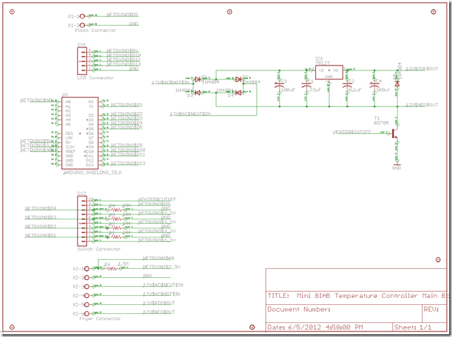
You can see the schematic for the circuit later in this article. Look for the Fryer Connector in the lower left of the schematic.
Driving the Relay
Next I needed to drive the relay which in turn would switch power to the heating element. The existing Fryer Control Unit used the 12V AC from the transformer and converted it to 12V DC to switch the relay on and off. I figured this would be perfect for me as well.
One thing you can’t easily do is use voltages greater than 3.3V with the Netduino controller, so I need to use a transistor to switch the 12V DC on and off to power the relay. This way I could safely drive the relay with a higher voltage without worrying about the Netduino.
I also needed to convert the 12V AC to 12V DC so I didn’t have to have yet another power source to drive the relay. Well this was pretty simple, all I needed was a bridge rectifier built from 4 diodes, a couple of capacitors to filter out the resulting wave and then run it through a power regulator to get a nice 12V DC output.
After a little research I came up with the circuit below on the right:
As you can see I apply the 12V AC signal to the bridge created by the diodes and then filter the resulting signal through a 100uF polarized capacitor and then with a .33uF capacitor before it connects to the the LM7812 voltage regulator. The output is then filtered with a .1uF capacitor along with a second 100uF polarized capacitor. The .33uF and .1uF capacitance values come straight from the LM7812 datasheet. The other two came from some rough calculations to ensure I had enough voltage stored to smooth out the voltage dips between the peaks in the modified output created by the bridge rectifier. I also cheated a little and pulled the values of the capacitors from the original control board when it looked like my calculations of 400uF was going to be a little too much.
The connection to the relay is then taken from the positive and negative leads of the filtered output. I then use a diode to prevent a reverse voltage on the circuit when the relay shuts down and the NPN transistor is used as a switch to allow the voltage to flow to the 12V relay when the Netduino raises Pin 9 high.
I also put a switch in series between Pin 9 of the Netduino and the transistor to provide a safety measure to make sure the system does not power up the heating element unintentionally. This was needed since the pins on the Netduino are all raised high when the unit powers up. Without it the relay could get power when the Netduino is powered on causing a dry fire burning the element out.
Connecting the Old to the New
With the circuit to drive the relay and heating element and the circuit to read the thermistor complete, I needed a simple way that I could run the old connections to the Netduino.
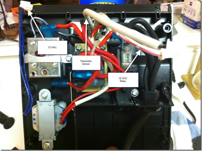
You might remember the picture above from my last post. Here you can clearly see that I needed to take 3 short leads and extend them to about 6 feet where the Netduino would be. To accomplish this I spliced the connections to the end of a Cat6 Ethernet cable. I used the following connections:
- 12V AC connections – Blue and Blue/White
- 12V DC connections – Orange and Orange/White
- Thermistor connections – Green and Green/White
The Ethernet cable is then connected to the breadboard via a RJ45 wall jack that connects to a series of screw terminals on the breadboard. You can see these connections in the schematic above in the lower left of the schematic labeled as Fryer Connector.
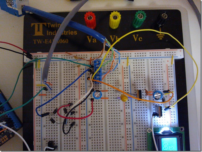
Here is a picture of the entire control circuit laid out on a breadboard connected to the Fryer:
You can see the RJ45 Connector coming into the screw terminals at the top along with the connections to the bridge rectifier and the return from the AC/DC Convertor on the right.
That’s about it for interfacing with the old Fryer Control Unit, In my next post I’ll discuss the Human Interface connections for the Temperature Controller as well as the LCD Display.
Till next time, stay sanitized and keep an eye on those fermentation temps and I’ll catch you for a pint around the keg.
Jim Lavin – Otaku Brewer


